
Remapping
Enables or disables the Remapping function (incl. Color Remap).
Some Fields such as the Spherical Field are symmetric, i.e., values increase in the direction of the Field’s center and then diminish. Visually, this effect can be depicted by this graph. This option should be disabled for the Linear Field. This option only serves visual purposes.
See Multiplier below.
Enabling this option inverts the Field’s effect. A valure range of 0.4 to 0.6 will, for example, be translated to 1 to 0 instead of 0 to 1.
The Inner Offset setting is displayed for the geometric Fields in the Viewport with an additional purple preview and can be modified interactively. This is the range in which the Field’s effect is the strongest, which then diminishes to 0.
For the other Field’s, an increasing value will more quickly raise smaller starting values to the maximum.

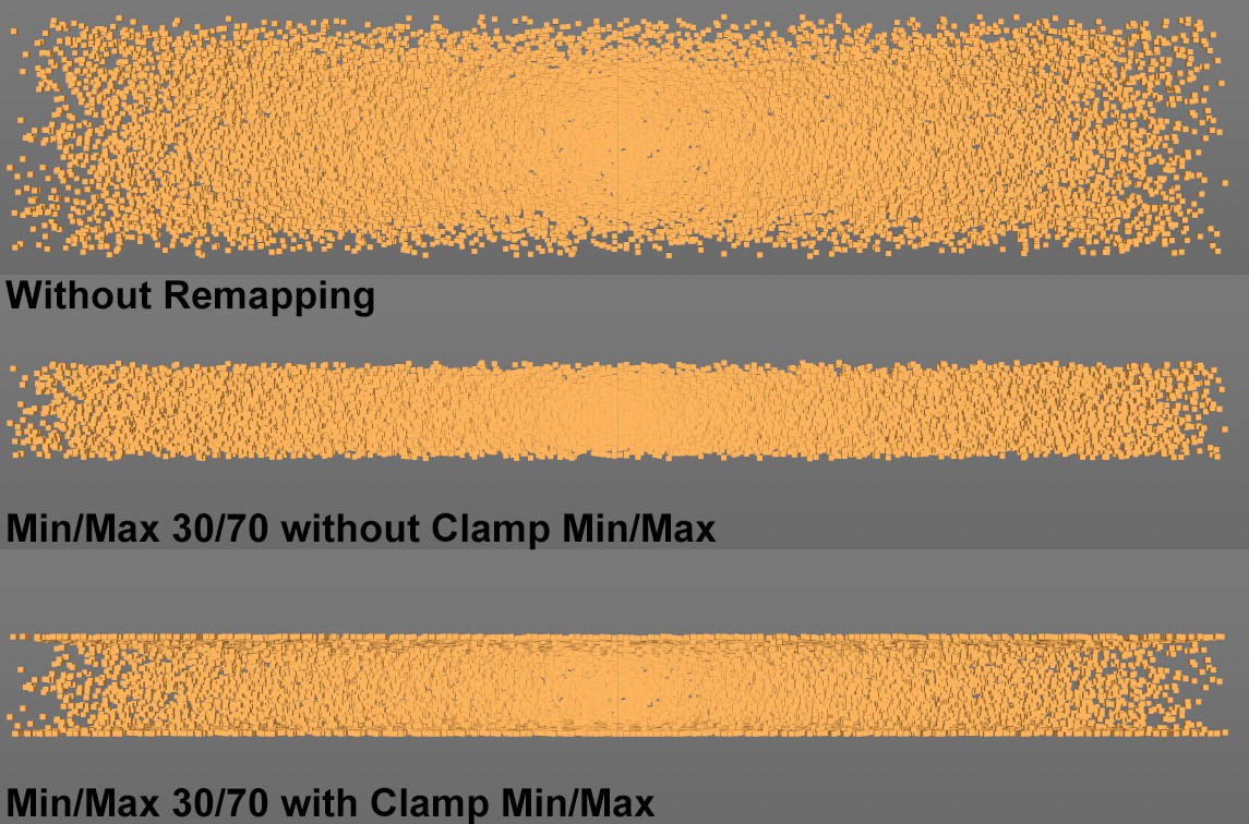 A Random Field (in a Plain Effector with Y offset) with both Min/Max modes (set to 30% and 70%, respectively).
You have the following options for how the start values should be treated:
- Clamp Min/Max enabled: they will be clamped
- Clamp Min/Max disabled: they will be translated to the new value range
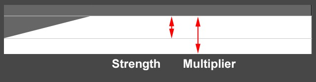
Opacity defines the strength of the Remapping exclusively between the Min/Max limits (see below) and the Multiplier value applies to the entire Remapping function.
Here you can select the mode with which the output values should be modulated. You can select from the following:
- None: The value transfer will take place linearly
- Quadratic: The value transfer will take place based on a curved defined by the Curve option, which controls the transfer from linear to exponential in both directions.
- Step: Values will be restricted to certain discrete values. The difference to Quantize is visible when the Min and Max values are modified: the number of steps remains constant but the value interval changes (see image below).
- Quantize: Values will be restricted to certain discrete values. The difference to Step can be seen when the Min and Max values are modified: the value interval remains constant but the number of steps changes (see image below).
- Curve: The value transfer takes place based on a freely definable curve.
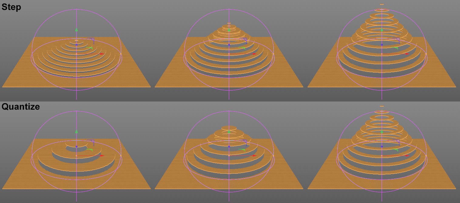 Regarding the difference between Step and Quantize: A Spherical Field controls a Plain Effector (which controls the Y position), an animation from Max[ [[0%] to 100% follows. Note the identical step interval with Quantize.
In this mode, the curvature of the value transfer curve can be adjusted.
With this setting you can define the steps for the modes Step and Quantize. This is an exact number of steps for the Step option and for Quantize only if Max is set to 100%.
Define the spline for the value transfer here.
If you want the spline to move along the X axis, enter a value greater than 0 here. In order for this to work steplessly, both the start and end values of the curve should have identical values.
The modifiable frame count defines how long the pass will take before it repeats.
Here you can define an offset for the curve. The length of the pass can be quickly adjusted here.
Use this setting to compress the curve horizontally (larger values) or stretch it (smaller values). A value of 200%, for example, will double the curve.