

Options
Note that several of the settings described below only work in certain component modes and will be displayed accordingly.
The bridges created using the Bridge tool can be subdivided as desired. This is especially important if you want to curve the bridge using the following Tension setting.
A Subdivision value of 0 will produce a linear bridge.
Use this setting to define the degree to which the bridge should be curved. Note that the Subdivision values must be greater than 0. The curvature direction orients itself according to neighboring edges / edge loops in consideration of various tool settings (e.g., Mode Start / Mode End).
A value of 0 will produce a linear bridge. Negative values can also be defined, which will invert the curvature.
Enable this option if you want to define separate values for the bridge's start and end. Otherwise, identical values will be used.
These modes represent the curvature transition between the selections to be bridged (if Tension and Subdivision are both set to >0; otherwise the bridge will be linear.:
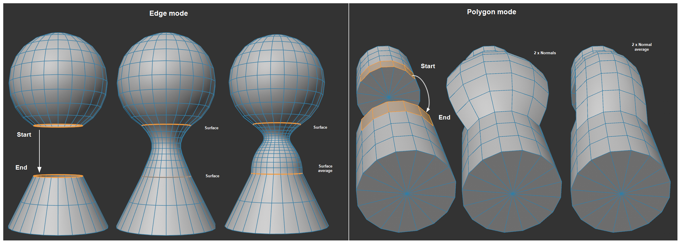 The described modes with the tool applied from upper to lower selection. Subdivision and Tension >0.
The beginning and end is defined by the mouse interaction. if you grab one edge it will be the start and the end will be where you release the mouse button.
The following options are available:
-
Surface: Recommended for connecting selected edges. The surface of the neighboring polygons will be continued (see left half of image above).
-
Normal: Recommended when connecting selected surfaces at their borders. The larger the Tension value, the more perpendicular the bridge will run to the polygon selection (i.e., increasingly along the polygon Normals) from start to end.
-
Surface Average: Like Surface only that a common, average direction will be set for the bridge at the start and end, respectively (see right part of left side of image above). This mode tends to result in less overshoot for the bridge.
-
Normal Average: Like Normal only that a common, average Normal will be assumed (see top right of image above).
If the bridge you created behaves strangely, e.g., if it runs in the wrong direction - for example from the start or end to the center of the object - try applying a interpolation sequence to invert the start and end selection.
Spin Steps[-2147483647..2147483647]
Normally, selections will be connected with their matching counterpart. First point of the first selection of the target selection, second with the second, etc. Modifying the Spin Steps setting will, for example, let you connect the first with the fifth. This can be seen in the image below.:
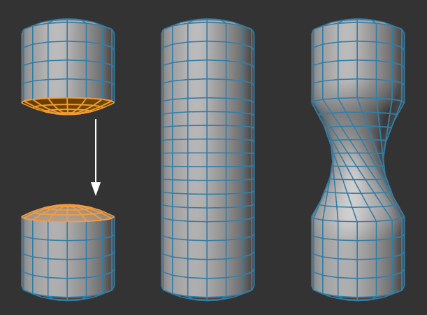 From left to right: initial state, Spin Steps = 0 and 5.
The edges to be connected must create a closed loop (for polygons it's the border edges).
The setting can also be used as with the Reverse setting (also in combination with it) in order to remove intersecting bridges.
For 2 selected polygons to connect or 2 edge loops, it can happen that the point sequence does not match and the bridge intersects and penetrates itself. In this case you can reverse the option to create a normal connection - the point sequence in one of the loops will then be reversed.
Also note in conjunction with this the previously described Spin Step setting.
If this option is enabled, previously selected separate edges or polygon islands will be connected with each other. This also works if the selections are currently not visible in the Viewport.
If this option is disabled, individual selected edges or polygons can be dragged onto others, whereby the bridge will be created. Existing selections are irrelevant.
This option can be temporarily switched interactively if you press the Shift key while dragging to create the bridge.
This option only has a function in Polygon mode and will maintain the originally selected polygons. Otherwise these will be deleted.
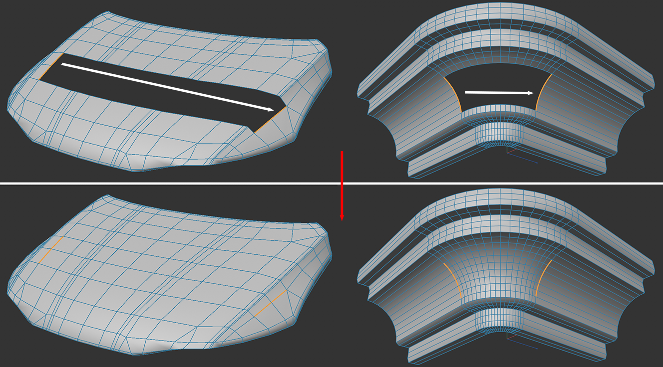
This mode first works only within "polygon holes" in Edge mode and ignores most other tool settings. Make a selection on the opposite edge in order to give this tool a clue as to how the loops should run.Opposing selected edge pairs will be given a loop matching the surrounding geometry. The best results are achieved when the number of opposing edges matches.
It can sometimes happen that both sides of a an edge selection on a polygon hole can have very differing edges. It may then be desired that the selected edge pairs be connected, as is shown in the image below.
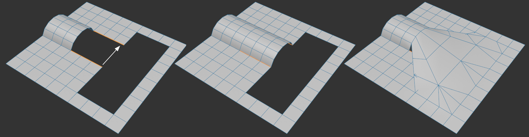 Left the initial state; center with enabled, right with disabled One-Sided Patch option.