

Object Properties
If you want symmetry planes to be displayed in the view, activate this option. The planes are displayed with respect to the Symmetry object in the respective axis colors (X red, Y green, Z blue).
You will then see exactly how the geometry is mirrored.
2 modes are available:
-
Planar: Objects are mirrored axially symmetrically along the directions defined by X, Y and Z.
-
Radial: This positions Child objects such as pie slices radially around the origin of the Symmetry object. Axis defines the axis of rotation.
Planar settings
For the Planar Type setting, you will find the specific settings described below.
With X, Y, Z the halves to be mirrored can be defined. The axes refer to the Symmetry object in each case.
- Off: Mirroring is not performed on this axis.
- + to -: The positive half of the axis is mirrored.
- - to +: The negative half of the axis is mirrored
Up to 3 mirror planes can be defined in accordance with the 3 dimensions - although in most cases one is sufficient (most objects are symmetrical only with respect to one plane: e.g., a face or a car body). Rotationally symmetrical objects such as a baseball bat will have 2 mirror planes.
Radial settings
With the Radial Type setting, you will find the specific radially symmetrical settings described below.
Select here the radially symmetrical axis of rotation around which the pie pieces are to be duplicated.
This allows the radially symmetric mirror planes to be rotated around the mirror axis. Activate Mirror to see an effect.
Source Slice[-2147483648..2147483647]
This setting is important, for example, if the Remove Outside option is enabled. It then specifies the pie slice within whose boundaries the corresponding object section is radially symmetrically duplicated. The pie slice is marked with an arrow:
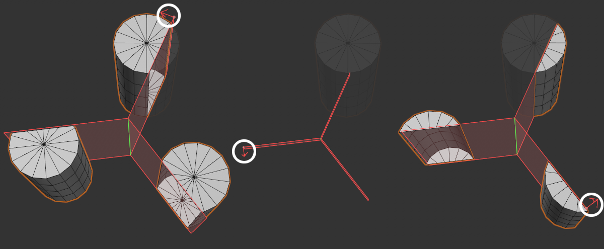 0, 1 and 2 for First Piece and their effect on Radial Symmetric Duplicate (Remove Outside enabled).
Enter here the number of pie slices within which radially symmetric multiplication is to be performed.
If this option is activated, an additional mirror plane is assumed in the center of each pie slice, which reflects planar symmetrically per pie slice.
General settings
The following settings apply to both planar and radially symmetrical settings.
If the option is activated, Generators - including Primitives - and Deformers are maintained. The Symmetry object then works like a Cloner object, except that it is mirrored (and overlapping object areas are not cut away).
You will recognize this functionality when you make the Symmetry object editable by pressing the "C" key. The object hierarchy remains unchanged when the option is enabled, while there are only polygon/spline objects when the option is disabled.
Attention: As a side effect, the matrix of the mirrored objects can be inverted (which can be seen in the Coordinates tab, where, for example, S.Y. will be set to -1). This can result in inverted normals as well.
This and the following two options are only accessible if Stay Parametric is disabled.
Welding can make a single object out of the duplicated object components considering the following options:
- Off: The objects remain separate.
- Crosses Plane: As soon as the object intersects the symmetry plane.
- On: Objects are always combined into one.
At first sight it may not make any difference visually, but at the latest when you make the symmetry object editable, you will see the difference in the Object Manager: Mirrored object halves consist of 2 separate objects or just one combined one.
Activate this option if a cut is to be made along the symmetry planes, then the next option can also be used to cut away superfluous elements.
If Cut Along Layer is disabled, duplicated components will simply be copied into one other.
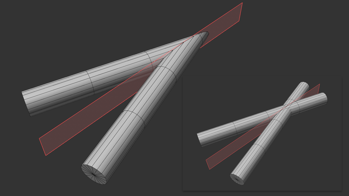
Define here whether object components beyond the symmetry plane should be cut off (left option enabled) or preserved (right option disabled).
This is especially useful if you already have a symmetrical object - e.g., a head - and want to work symmetrically without first deleting one half of the head, as was previously the case with the Symmetry object.
This command makes modeling more convenient and helps you connect to a symmetry plane and more easily position close points (distance defined by tolerance) on the plane:
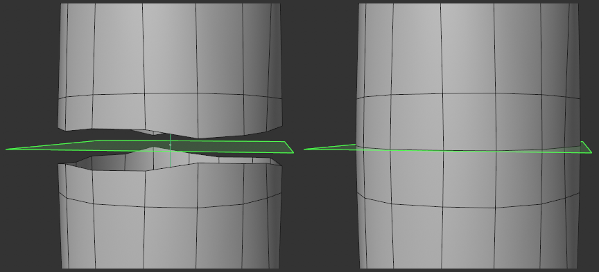 Before and after calling up Cut Along Plane.
Cut Along Plane only works with boundary points (i.e. points that belong to a maximum of 2 polygons) and only with the points of polygonal objects - i.e. not generator-produced objects, for example.
These two commands allow you to copy settings that you either make here in the symmetry object to the global symmetry settings or copy global symmetry settings to the current symmetry object.
Since both are similar but not identical, only the settings that make sense for both are applied.