

Caps and Bevels
What are Caps? Various generators, such as the Extrude object, create a polygonal object from splines by moving the spline along an axis, for example: a Circle spline becomes a cylindrical "shell". A closure must be found at the beginning and end of this cylinder: this is provided by the caps (shown in stripes below), thus forming a closed object. The transition between the caps and the shell can be designed in different ways. In the following, this transition is called "bevel areas" (colored red):
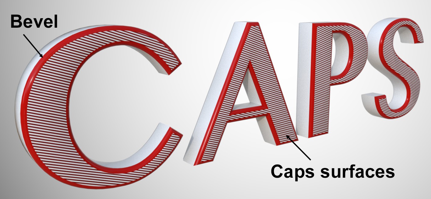 A Text spline in an Extrude object with beveled cover areas.
Migrate
If you load older scenes (< R21), this button will be displayed. First, the scene is loaded with the old (working) settings for the old cap surfaces.
If you would like to switch to the new functions described below, click on this button. An attempt is made to produce a similar result.
These two options can be used to define which caps surfaces should be created. If no caps surfaces are present, no bevel surfaces can be created.
Enable this option if different Start and End settings will be applied to a bevel. A second group of settings will be added at the bottom of the menu. Otherwise, the same bevel will be applied to both start and end.
Don't be surprised that many of the following settings are shown double. These are identical settings for the front and rear Caps surfaces.
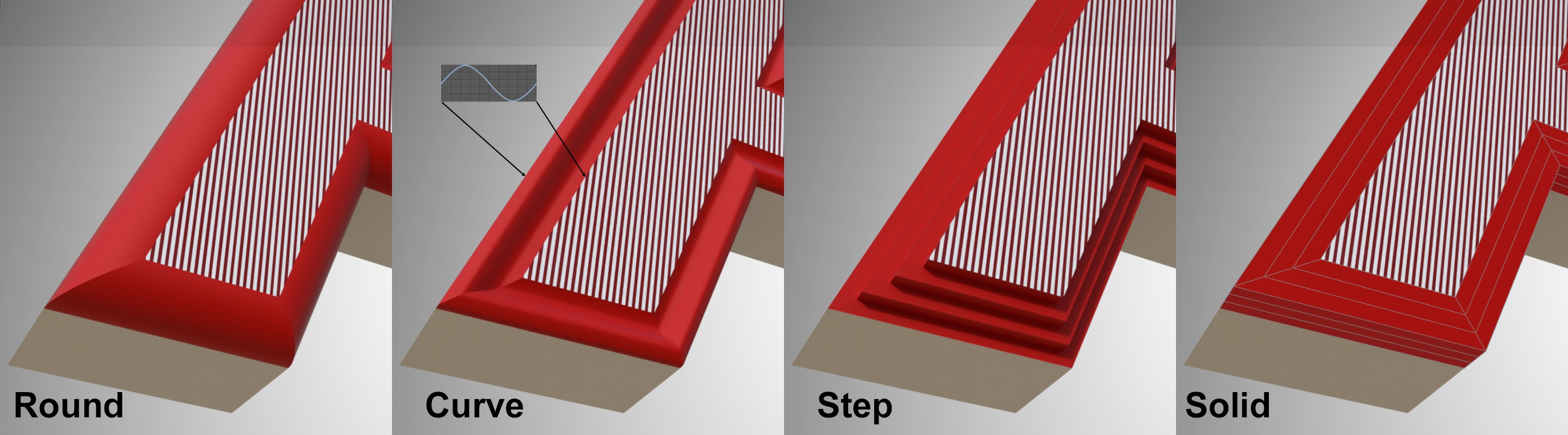
The transition from caps surface to shell can be given just about any type of rounding. You can select from the following options:
- Round: The transition will be rounded (the radius can be defined using the Tension setting, including negative values).
- Spline: The transition is defined using a freely definable curve (see below)
- Step: The transition will be stepped. The number of steps is defined using the Subdivision value.
- Solid: Doesn’t actually create a bevel but rather subdivisions - defined using the Subdivision value - in the bevel range defined by the Size value, which creates a rounded transition when using a generator in a Subdivision Surface object.
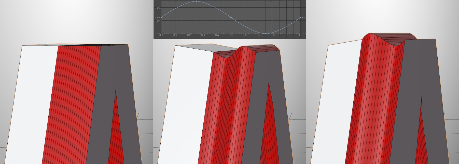 From left to right: Amplitude 0, negative value, positive value
Use this setting to define the overall size of the bevel. The larger the value, the more the caps surfaces will be pushed outwardly, which will cause the bevel surfaces to grow. If set to 0, no bevel will be created; the caps surfaces will complete the shell with a sharp edge.
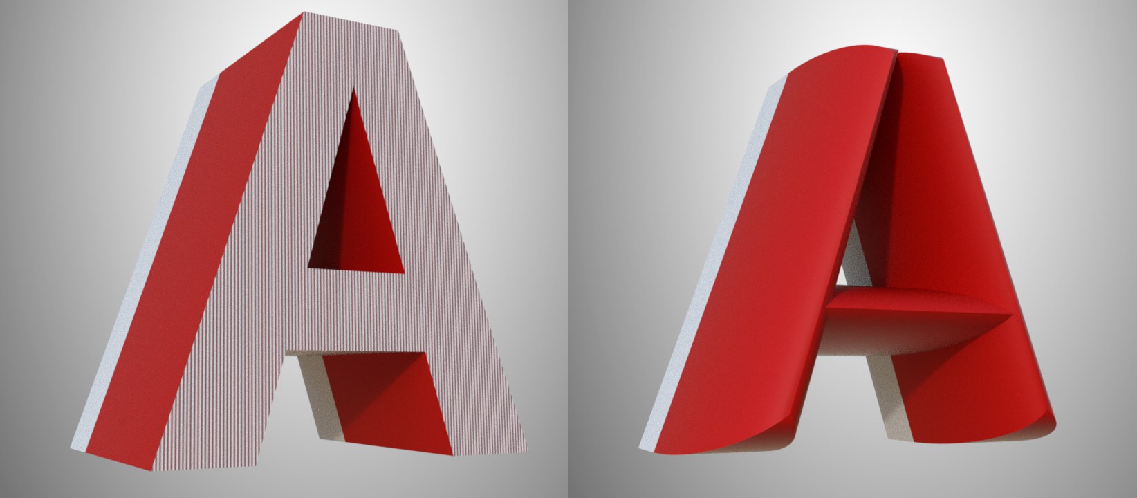 Enabled : Extrusion left with Size set to 0, right at maximum.
If this option is enabled, the caps surface will be extruded according to the defined Offset value.
If Shape is set to Spline, this curve can be defined in just about any shape. Here are some examples:
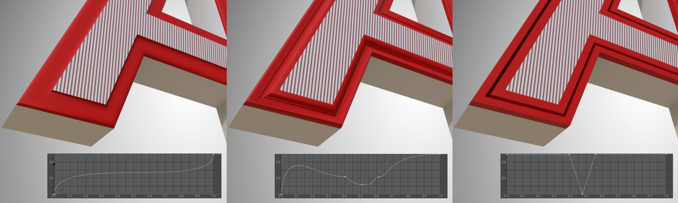
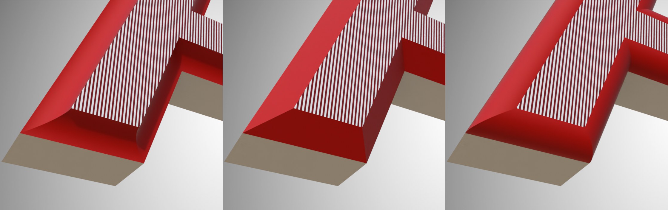 From left to right: -100 and 100 for Tension.
This setting can be used to control the curvature of the bevel surface. Negative values push the curvature to the inside, positive to the outside. A value of 0 (or Subdivision = 1) will produce a chamfer.
If Shape is set to Spline, Offset is greater than 0 and Size = 0, the following effect will be produced: The caps surface will be extruded outwardly and the Tension defines the amplitude of the curve:
From left to right: Tension = 0, negative value, positive value.
Use this setting to define the subdivision in the bevel area. Depending on the complexity of the bevel shape (e.g., Shape set to Curve), this value must be increased in order to achieve a clean shape. A value of 1 will always produce a straight chamfer (exception: Shape set to Step),
These two commands can be used to save the bevel values in this section as presets and load them again.
General details regarding the Preset System in Cinema 4D can be found there.
Note also the presets already included that offer a wide range of shapes.
Normally (option disabled), beveling is done using caps surfaces that decrease in size and the contour (e.g., Text spline) remains constant. If, on the other hand, the caps surfaces should remain constant in their size, this option should be enabled. The contour size will increase correspondingly. Especially for very detailed shapes or text where very little space is available for inner contours, beveling can take place on the outside.
No control over self-intersection is available.
This option offers a very useful function. If you remember how caps surfaces/fillets worked in previous versions, you will know that larger fillets often had intersecting mesh that made the surface useless:
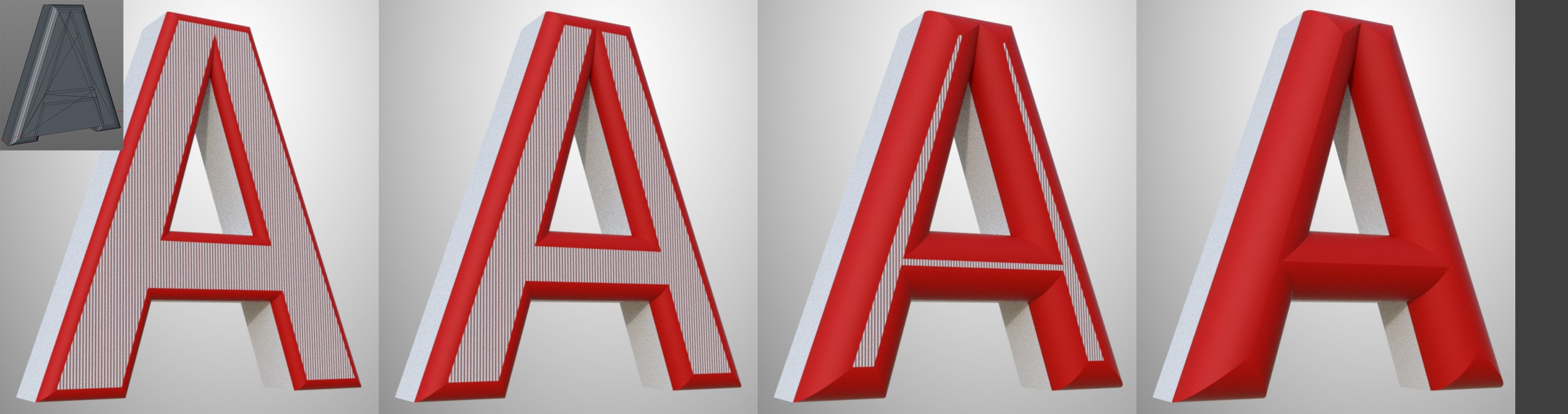 If the bevel Size is increased, the caps surfaces decrease in size from left to right until the bevel ends in a closed edge. At the top left you see the result in older versions.
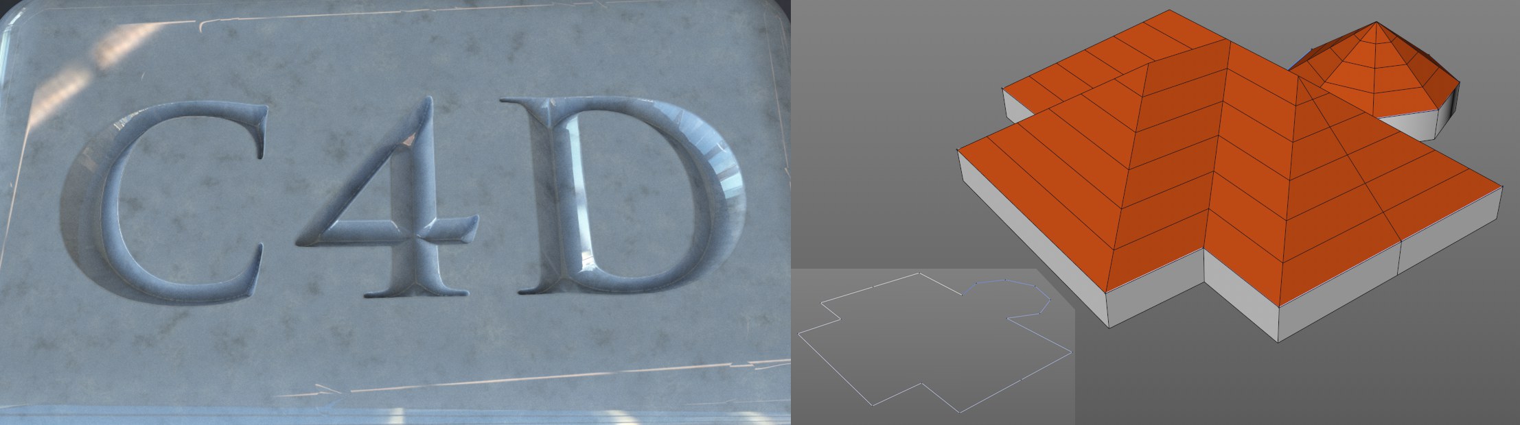 Avoid Self Intersections can help in many situations: chiseled text is not a problem anymore and creating hipped roofs using a spline as an outline is quickly done.
For rare instances in which this function produces unwanted results, it can be disabled.
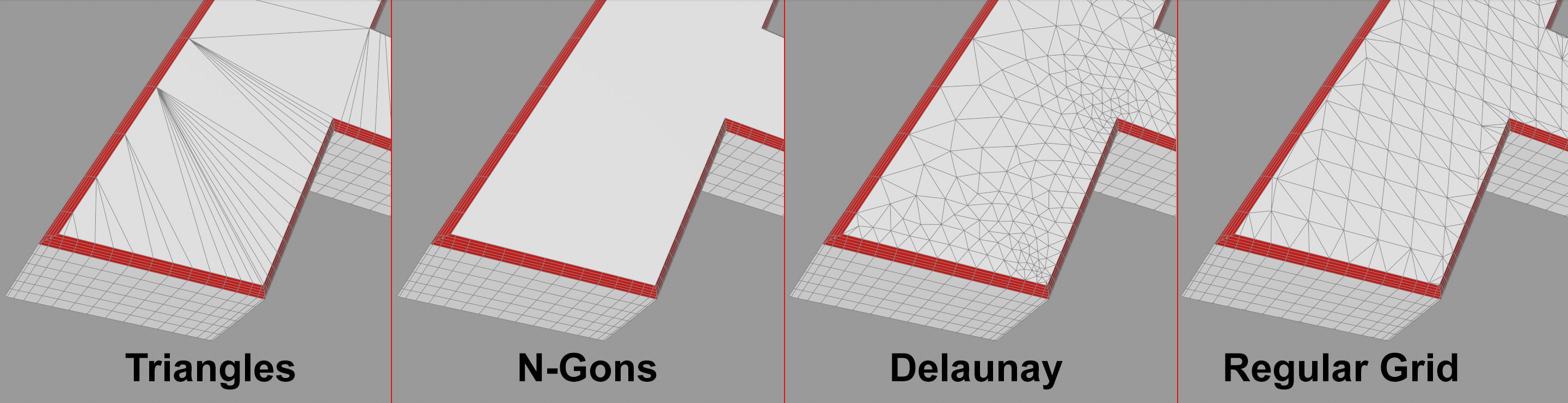
Here you can define how the caps surfaces’ mesh should be shaped. Triangles/Quradrangles are like the earlier Cinema 4D modes (prior to R21) that produce triangles and quads, respectively. N-Gons creates a single polygon that looks like Quandrangles internally.
For the first 3 modes, no new points will be created on the caps surfaces. The result: long triangles will be created that can lead to problems for shading or deformations.
As a rule of thumb: If the caps surfaces will not be deformed you can use N-Gons, otherwise Delaunay. Note also the subdivision of the splines involved that can be affected via the Intermediate Points setting. It is often better to use Uniform. Then, the linear spline segments will also be subdivided, which is usually critical for deformations.
Delaunay adds a triangle mesh to the caps surfaces with an inner angle that is similarly large, which prevents long, bothersome triangles. Such meshes are easy to deform without generating unwanted artefacts:
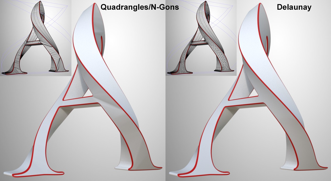
Delaunay offers several settings (see below).
If Regular Grid is selected, the caps surface will be made up of polygons of similar size arranged in a uniform manner. What is this good for? Let’s say you have 2 animated splines beneath a spline mask that combine to create a common spline that in turn lies in an Extrude object. The caps surfaces have to change in the course of the animation. If Delauney is selected, points on the caps surfaces can jump randomly due to the adaptive nature of the effect. This effect is reduced drastically if Regular Grid is selected.
When creating caps surface triangles, the triangles’ size on the outer and inner edges is initially defined by the subdivision (Intermediate Points) of the base spline. The triangles can increase in size approaching the interior (in some cases they can become smaller). As usual, it’s a good idea to have as few polygons as possible. The following distribution of polygons results from a uniform spline subdivision:
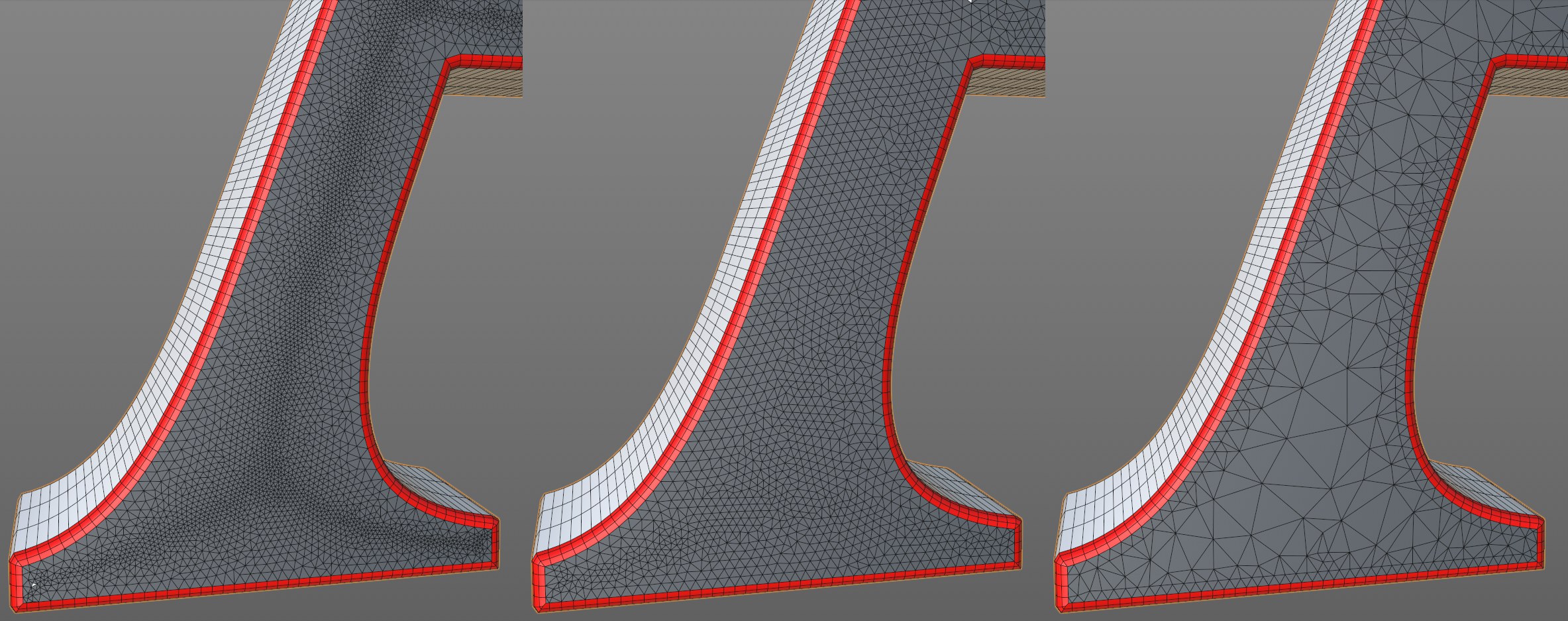 From left to right: none, middle and high Density values.
The result at the right is the most desirable.
The smaller the Density value, the larger the triangles in the interior of the caps surfaces and vice-versa.
Be careful with Density values that are too high: these are rarely of any use.
If Tessellation Type is set to Regular Grid, the Size setting will be made available. This is used to define the polygon size for the caps surface.
Enable this option to create four-sided polygons. No caps surface points will be modified. Some triangles will nevertheless be created, so you can’t assume you will have only quads.
If this option is enabled, Phong break edges (see also Phong Break Selection) can be assigned at the Start and End surfaces. The transitions from shell/caps surfaces to the bevel surfaces are then somewhat more accentuated.