

Weights
You use these settings to control the orientation of the calculated pulse splines. This is particularly important if the output spline consists of several segments. The settings here then influence the length of the pulse splines and their displacement.
Here you will find two modes:
- Tags: You can assign Vertex Map weightings for all spline points on the output spline and then enter the name of the corresponding Vertex Map Tag here, or assign it directly from the Object Manager using drag & drop. The pulse splines then spread along the output spline according to the weighting curves between 0% and 100%. This is the perfect method, for example, for branching tree structures that have been composed of several segments. If the spline points on the branch forks have the same weighting value, the pulse spline will also appear to split at this point and be routed to the connected branches at the same time. You will find an illustration of this below. This mode is also interesting because some capsules already automatically provide such vertex maps, which can then be used directly here.
- Raw Spline: Further Mapping settings can be made here, which the pulse splines should be based on. For example, the length or the order of the segments at the output spline can be used for control.
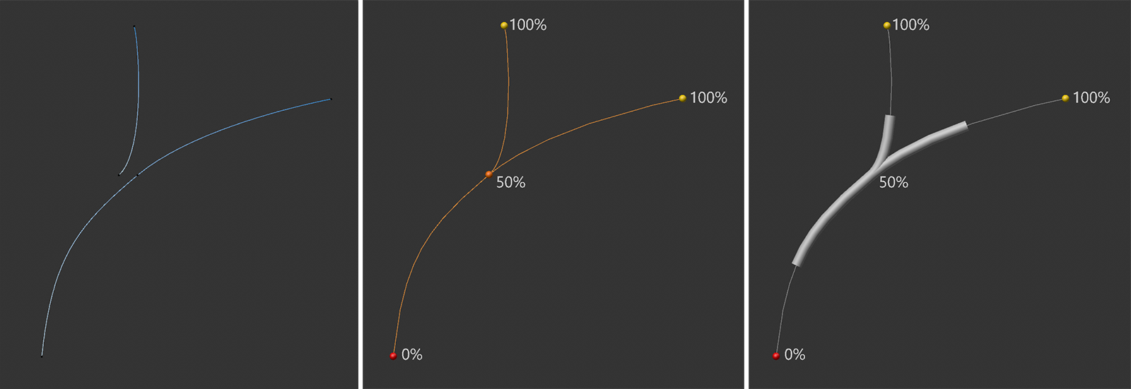 On the left you can see the two segments that have been combined within a spline. As can be seen in the middle illustration, these segments form a branch fork. Vertex Map weightings have been applied to them so that the points of contact between the short segment and the longer branch segment have the same weighting value (here 50%). As can be seen on the right, the pulse spline then naturally splits at this branching point.
Here you can enter the name of the Vertex Map Tag if you use the Tags mode.
In Raw Spline Weights mode, you set here how the spline segments are to be evaluated at the output spline:
- All 0%-100%: All spline segments are assigned pulse splines simultaneously and separately from each other.
- Relative to Longest (Aligned On 0%): The longest spline segment is used as the benchmark. With a shift of 50%, for example, all pulse splines are then shifted by half the length of the longest segment, starting from the respective starting point of each segment. If the segment lengths vary greatly, this can of course also lead to the pulse splines having completely covered the short segments after a few animation frames, while the pulse splines on the longer segments can still be seen for longer.
- Relative to Longest (Aligned On 100%): The principle is the same as the previous mode, except that the distances are calculated from the end of the spline segments.
- Subsequent: All segments on the output spline are run through a pulse spline one after the other and not simultaneously as in the previous modes.
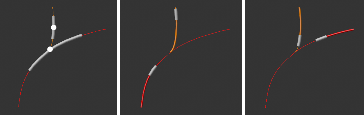 The 'All 0%-100%' mode is shown on the left. The centers of the pulse splines are placed identically when converted to the lengths of the segments. The 'Relative to Longest (Aligned On 0%)' mode is shown in the center. The red spline segment is the scale. The pulse displacement measured from the beginning of this segment (marked thicker in red here) is transferred identically to the shorter segments (marked thicker in orange here). In the 'Relative to Longest (Aligned On 100%)' mode, this distance is measured from the end of the longest segment (marked thicker in red in the right-hand illustration) and transferred identically from the end to the other segments (as can be seen from the thicker highlighting on the vertical segment).