

Group
Here you select the criterion according to which the splines are to be connected:
- Next: The order in which the splines are connected to each other is determined by the order in which the splines are assigned to the capsule. This allows you to determine the order of the connections yourself by individually rearranging the spline geometries.
- Closest: The distances between the last point of the previous spline and the first point of the following spline are evaluated. The order in which the splines are connected to each other is therefore determined by the distances between the spline ends and not by the order of the spline assignment on the capsule. In this mode, additional Min/Max values are available to only allow connections between the spline ends that are within a certain distance from each other.
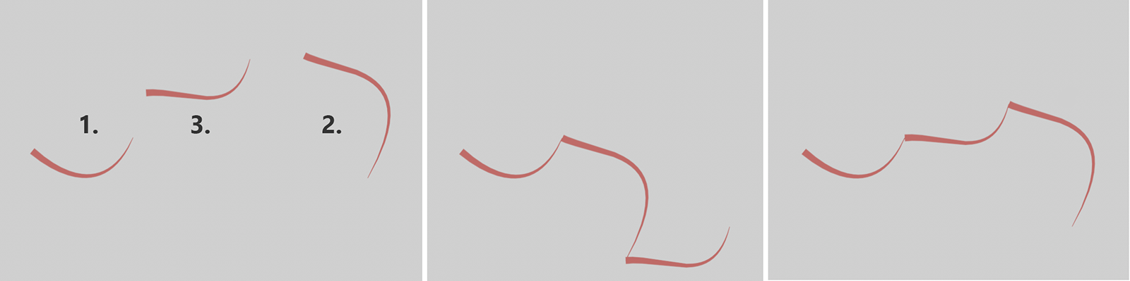 The three individual spline geometries used with the capsule can be seen on the left. The numbers there describe the order in which the splines were assigned to the Node or grouped under the capsule in the Object Manager. The result of the Next mode is shown in the middle and the result of the Closest mode on the right, where the order of the splines no longer plays a role.
This option is only relevant if the assigned splines consist of several segments. For example, think of a text spline of the letter O. This spline consists of two segments for the outer boundary of the letter and its inner opening.
If the option is activated, all segments within the splines are treated as independent spline geometries and may also be moved to new positions. If this option is switched off, the shape of the splines made up of segments is retained. Only the start point of the first segment and the end point of the last segment are then taken into account for the connections.
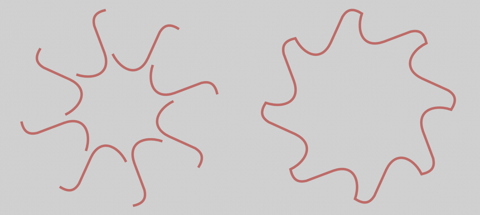 Here, a spline was drawn in the form of an S-curve and then duplicated in a circle using an Array generator. The array object has been subordinated to a Connect object. This turns the spline copies into segments on a joined spline. Finally, the Connect object is grouped under the Join Spline capsule. On the left you can see the result with the option for Explode Segments switched off. The segmented spline remains unchanged. The option on the right has been activated. All segments are now recognized and arranged into a coherent structure.
These settings are only available for Join Closest and allow you to specify a minimum and maximum distance between the spline ends between which a connection should still be possible. The following image shows an example of this. A Sweep Object is used to display the splines where the scaling of the Circle profile used has been reduced at the end of the splines. This makes it easier to recognize the course of the splines (thick to thin) and the arrangement of the spline connections.
 Three splines are connected here. The Bridge mode was used, whereby the splines remain in their original position and only connections between them are regenerated. Increasing the Min value can suppress connections that have a shorter distance. This can be seen in the center and on the right. The Min value was gradually increased so that the relatively short distances between the outer and middle splines were finally completely ignored. The Max value must be correspondingly large so that connections can still be created at spline ends that are further apart.
This option is only available for Join Closest and specifies whether only the end points of a spline can be connected to the start points of another spline or whether only the distances between the end points of the splines should play a role for the connections (activated option). If the option is activated, connections can also be made between two start or two end points if these are within the distances defined via Min and Max. As can be seen in the following illustration, the order of the points on the resulting spline is corrected in each case and can then also deviate from the order of the points on the initial splines.
 On the left you can see the three splines used, whose point sequence is represented by the thick to thin gradient. Connect Either End was switched off in the middle and activated on the right.
Use this setting to define the way in which the splines or spline segments are to be connected to each other:
- Stack: The position of the first spline remains unchanged, while the subsequent splines are moved so that their starting points are at the positions of the end points of the previous splines.
- Bridge: All splines or spline segments remain in their original position and the gaps between them are bridged by new spline sections. Their shape can be influenced by the Tangents value.
 The three spline curves used can be seen on the left. The Stack mode was used in the middle, whereby the second and third spline change their positions in such a way that a new course is created starting from the first spline. In Bridge mode, all splines retain their positions and only the gaps between them are filled with new spline sections (shown on the right). A Sweep object was used to visualize the splines, where the scaling was reduced towards the end. In this way, the individual splines and segments can be recognized by their arrow shape.
This setting is only available if Mode Bridge has been selected. In this case, this percentage value then controls the intensity of the tangents at the ends of the inserted spline sections between the original splines. Small values produce a more linear connection, whereas larger values can also result in softly curved transitions. Depending on the length and rotation of the tangents at the end points of the original splines, this can also lead to overlaps or an overshoot in the course of the resulting spline. In such cases, an individual adjustment of the Tangent value is necessary.
By the way: You can also use an alternative method to round off the transitions at the splines using the Chamfer option.
Here you specify whether the individual sections on the resulting spline should be permanently connected to form a continuous segment (activated option) or remain as separate segments (deactivated option). Activating this option also reduces the number of points in the spline, as points at identical positions are automatically combined into one point.
The following image illustrates this as an example. Once again, a Sweep Object with a circular cross-section was used to display the spline. At the Sweep, the cross-section was automatically reduced towards the end of the segments in order to be able to read the point sequence and segment boundary from the resulting arrow shape.
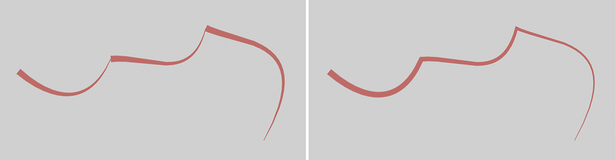 The option is switched off on the left. The original splines remain on the resulting spline as separate segments. The option on the right has been activated. The individual splines are thus joined together to form a continuous spline with a segment.
These settings can be used to round off the overlaps between the original splines or spline segments. Unlike when using the Tangents value, this creates additional points on the resulting spline. Please note that the Tangents value should be 0% in Bridge Mode for Chamfer rounding to work.
By activating the Chamfer option, the Chamfer Radius can be used to set the strength of the rounding. If you prefer a linear bevel instead of a rounded transition, activate the Flat option.
This is used to connect the last points of all created segments with the first points. Please note that this also applies to splines that have been filtered out by using the Min and Max settings in the Closest Join mode and are therefore not actually included in the resulting spline.
In addition, activate the Weld option so that adjacent segments are combined into one segment and the closing of the splines actually only refers to the open ends of the joined splines.